
1) what is single line diagram of substation ?
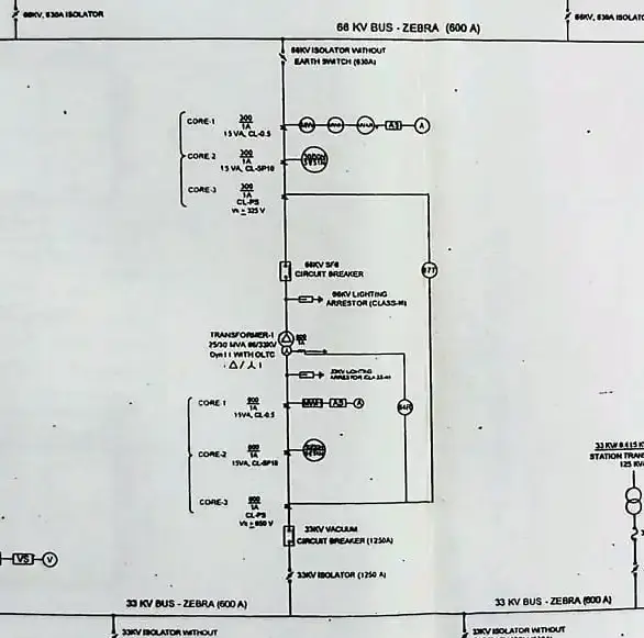
Single Line Diagram Of The Substation Is A Remarkable Drawing Containing Switch Yard Equipment With Symbolic Notification And Its Rating Of Equipment And Protective Equipment Purely Identification Of Its Position Via Single Line Coded Against Actual Multi-Phase Drawing Which Is A Little Bit Complicated To Understand Of Any Site View Of Symbolic Notification.
Article Content
Toggle
SLD is a clean and understanding version of drawing with its various symbolic notification of switch yard equipment like power transformer, current transformer, potential transformer, isolator with earth blade, lightning arrestor, bus bar position and its rating, circuit breaker, etc.
2) Advantages :
2.1)EASY TO UNDERSTANDING ELECTRICAL SIGHT
2.2) FASTER REACH OUT OF ANY EQUIPMENT WITH SOME DETAIL
2.3) QUICKER MAINTENANCE AND TROUBLESHOOTING
2.4) SOFT UNDERSTANDING OF NEWCOMER TEAM MEMBER
2.5)STURDY AND HANDY LOOK OVERALL SITE BLUEPRINT
3) symbol using in single line diagram of substation
3.1) isolator switch

- An isolator switch is a switch that connects the circuit from various equipment to each other and also disconnects the circuit from each other switch yard equipment, An isolator switch is a key role equipment in a substation because, during operation and maintannnce isolating from each other device, we always use this switch during maintenance purpose. this switch is rating its current carrying capacity and we are also known as off off-load switch because during on-load we can’t open them because of the safety of the personnel and the life of the switch conducting rod.
- isolator majorly many types available but most of use 2 types widely used in subtation are 1) verticle single break and 2) horizontal double break, These 2 types have their own purpose of use with location and current carrying capacity.
3.2) transformer

the transformer is a king equipment in switch yard and single line diagram of substation because transformer transforms electrical power from step up or step down whenever necessary requirement depending upon its type and location on where to use it, The transformer transforms in various steps in voltage and is independent of current and frequency, the voltage of the system also can be stepped by its tap changer which is an inbuilt feature of the power transformer and power transformer also have many protection and relay system and various monitoring parameter.
transformer mostly use 1) star – delta type for step-up type transformer
2) delta-star type for distribution purposes
3.3) current transformer

the current transformer in short C.T. has to show the system nominal current in our energy meters and panels relay.in c.t. has two core and three core types used on demand of the system, Whenever we used it in the transformer section always used three cores due to one extra core protection of differential protection via a relay of the transformer. CT function is current measuring and protection current via relays when the system makes unbalanced or faulty condition, and always connect series wise and markable on contact P1 and P2 on both contacts.
type: live tank and dead tank CT also various types based on usages mostly delta-star type used.
3.4) potential transformer

A POTENTIAL TRANSFORMER is a type of instrument transformer and is a useful device in switch yard equipment. PT is a voltage transformer, mostly PTs in the switchyard have a secondary 110 v line-to-line voltage present and PT always connect in parallel with other instrument. PT is used in voltage measuring and voltage step down to 55v per line whenever benchmark as per area and country. pt mostly step-down type used in most places.
3.5) LA- lightning arrester

LIGHTNING ARRESTER is a protective equipment type with many types like horn gap, rod gap, sfear gap, thyride disc mounted etc. When normal current or power is transmitted via LA there is no earth pass in the system, Whenever travelling surges and switching high surges or monsoon season heavy lightning occurs then LA comes into action and surge current bypass via earth, the connection provided in LA body. LA is connected across the transformer, generator and both ends of the transmission line. LA is always connected across or parallel to the system.
3.6) bus bar

ELECTRICAL BUS BAR is a location of circuit extension and connects various equipment single line diagram of substation in live parallel circuits like a transformer, alternator, or other protective equipment like ct, pt. bus bar rating is the largest rating holder of all switchyard equipment bcoz all of the equipment power connects or transmits via the bus bar, so the bus bar has have largest rating for stranded ACSR cable using high mechanical strength.
medium type substation has panther and zebra type conductors used in bus bar systems up to 650 amp current.
3.7) circuit breakar
CB is a very important device in single line diagram of substation . circuit-isolating electromechanical switch. circuit breakar operates in sub transient state whenever a fault occurs. we can operate and use CB when maintenance and isolating line then soft switch off by this equipment and whenever fault occurs CT senses extra current via a relay setup then commands to breaker to trip then our breaker trip disconnects the faulty circuit within a few microseconds.
circuit breakar has many types like air blast cb, vacuum cb, and sf6 cb. mostly and most convenient type is sf6 it has larger current disconnect property and non-inflammable gas sulfur hexafluoride fill around the content of brakes for arc quenching medium. sf6 type CB is the most reliable and safe circuit breaker on his classificationvery
3.8) feeder
FEEDERS are called distributors in single line diagram, those mediums distributed to consumers of electricity in the network. feeder design made by it ampers loading details of individual load calculating and size. most feeders are ACSR starnded cable or XLPE insulated cable that have 3 3-phase 3 wire scheme of reaching power from the substation to pole mounted distribution substation. then after reaching pole mounted distribution substation its secondary output 3 phase 4 wire for individual consumers, as per requirement.
4) faqs:
4.1)How to draw (sld) single line diagram of substion 66kv substation / 33kv /11 kv substation
drawing of single line diagram of the substation in various ratings like 66kv and 33/11 kv substation via primarily information about switchyard equipment with the above figure and put them as per his work area and connect as per her property and read more above symbol description section
4.2) Is single line diagram containing all phase
No, single line diagram contains only a single line indicating all phases virtually and is easy to understand