
What is Armature Winding?
→ Any motor or generator has two types of winding presence in it. 1) Stator winding 2) Rotor winding. in this tutorial, we fully discuss rotor winding called Armature Winding.
Types of Armature Winding
→ There are majorly two types armature winding.
1)simple wave winding.
2)simple lap winding.
Wave windings:
→ in this type armature coils are connected in series through commutator segments. so, so armature winding devided into two parallel path irrespective no of pole and in the machine. keeping in mind that if there Z armature conductors , then Z/2 conductor in series will be in series in each parallel path and each parallel path will carry armature in divided way that express as Ia/2 .
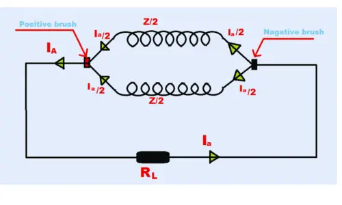
In above figure of simple wave winding we can arrive short conclusion describe below.
→ Important Points of Wave Winding
- Two parallel path irrespective no of pole of machine.
- each parallel path has Z/2 conductor in series ( Z= total no of armature conductors.)
- e.m.f. generated = e.m.f./ parallel path.
- total armature Ia=2×current in parallel path.
Lap Winding :
→ in this types of armature winding arrange armature coils are connected in series through commutator segment in such a way that armature coils divided into many parallel paths the no. of machine poles.
suppose , Z = conductors.
P = poles.
Ia = total armature current.
then there is P parallel path into armature winding. each parallel path containing Z/P conductor in series .each parallel path carrying current of Ia/P . just assume that is P= 5 so there are 5 parallel path in lap winding of armature.
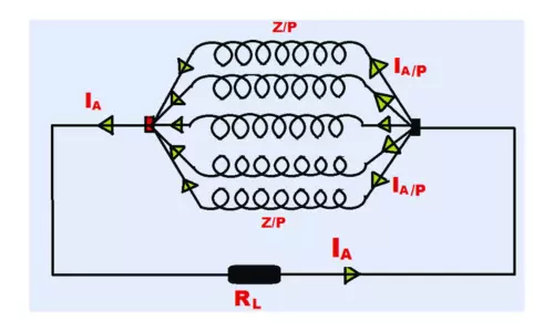
In above figure of simple lap winding, we can arrive short conclusion describe below.
→ Important Points of Lap Winding
- there are many parallel paths as same as number of of poles of the machine.
- each parallel path has Z/P conductors in series. ( Z = armature conductors.)(P = poles.)
- e.m.f. generated = e.m.f./ parallel path.
- total flow of armature current Ia=P×current per parallel path.
Selection of Armature Winding
→ Small Machine current carrying capacity is less and not a abnormaly high , then in order to obtain suitable voltage wave winding often use for this type machine.
→ Large Machine suitable voltage are easily obtained because relatively large no. of armature conductor Z available and current capacity is more high. Then larger current capacity type machine always use lap wound type armature.
Armature winding Resistance
→ The Resistance Offer to Active Circuit by Armature Winding is called armature resistance, and its represents Ra.
→overall armature resistance offer by two types.
- resistance of armature resistance.
- resistance of positive and negative brushes.
both resistance depends upon construction of the machine , except small machine its armature resistance value is generally less than 1Ω.
Some Used Terms:
Field System :
→ The function of field systems is produce uniform magnetic field for armature rotates. field system consist of number of salient types pole arranged by even number fix in yoke. the yoke is made by solid cast steel metal and pole pieces composed of stack lamination also field coils mounted on pole and able carrying dc or ac current . field coils are connected manner is opposite polarity from poles.
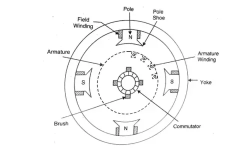
Armature Core :
→ Armature core is placed machine shaft and able to rotate between field poles. armature core consist of slotted soft iron laminations that forms of cylindrical way. each of lamination coated with electrical insulation, the purpose of laminating of insulation is to reduce eddy current loss.
Armature Winding :.
→ slots of armature core hold insulated conductors that are connected in suitable manners at his also known as armature winding. armature winding is actual working e.m.f. is induced. Armature conductors connected in series – parallel manner , if conductor connected in series for increase voltage and armature winding connected in parallel for increase current. armature always closed circuit winding.
Commutator :
→ Commutator is mechanical converter ( rectifier) device used for convert generating A.C. voltage transform into D.C. voltage across the brushes. The commutator is made with copper segments insulated from each others by mica and mount on shaft of the machine. Armature winding is solder to suitable manner to commutator segments to rise the armature winding.
Brushes :
→ the purpose of using brushes in any machine to contact between commutator segments and external load circuit or supply circuits. the brushes made of carbon and rest on commutator. the brush contact pressure adjust by spring . mostly carbon brushes prefer because carbon is good electrical conductivity of electricity and soft material so , no any damage or scratches on commutator. sometimes needs more conductivity then mixes some high grade copper with carbon.
→ if brushes pressure are high then high friction with commutator segments and create heat on it, other side pressure low is create poor connectivity to external source.
→ machine is acting as generator , brushes carrying current to external circuit. if machine acting as motor it feed supply to armature via brushes.
Armature reaction:
→ Current flowing through armature conductors creates magnetic flux and known as Armature Flux. if armature flux distort and weakens the flux coming from the poles this distrortion and field weakening takes place motor same as generator. this armature flux effect main flux from pole is called Armature Reaction.
→ when generator is unloaded a small current flow from armature does not affect main flux. when generator loaded the current flowing through armature build up own flux and counter to main flux .
Disadvantage of Armature Reaction :
- distortion and weakening main field .
- fully loaded generator increase current and falls generated e.m.f. due armature reaction.
Conclusion:
→ In conclusion, ElectricGuide.com’s insightful exploration of armature winding demystifies the complexities of rotor winding, offering a clear distinction between wave and lap winding. The comprehensive guide, enriched with terminology and practical considerations, equips readers to make informed choices in selecting and understanding armature winding for motors and generators.
FAQ’s
- Why mostly armature winding place on rotor?
→ mostly armature winding kept on rotor because to easily faciliate commutation and our machine circuit keep simple.
- Is armture lamination required?
→ armature lamination require to reduce its eddy current loss.
- Why carbon brushes used with commutator?
→ carbon have good electrical conductivity and softer and lighter material which easily pressurise by spring force and well lubricates commutator .
- Which material preferred for making aramature?
→ silicon steel used for making armature.
- Is armature reaction good or bad?
→armature reaction is reduced 10% main flux and increase overall current then falls generated e.m.f. so armature reaction isn’t good for generators.