
what is ideal transformer ?
An Ideal Transformer Is Called Which Transformer That No Losses At All, And Total Incoming Power Is Equal To Total Output Power. Ideal Transformer Has No Internal Losses And No Magnetic Leakage Flux Exist In Ideal Transformer.Here We Discuss About What Property Needs For Become Transformer To Achieve Tag As A Ideal Transformer.
Article Content
Toggle
ideal transformer condition:
- no winding resistance
- no leakage flux : same flux linkage to other windings
- no losses in the core
ideal transformer cannot exist in nature but only realising and aspecting in our minds. where practical transformer we have use their property very close to ideal when we kept above all parameter in mind. see how ideal transformer perform in no load condition.
ideal transformer no load condition
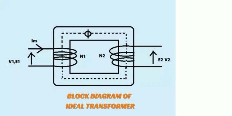
lets seconadary open circuited , then under this condition primary winding coil made pure inductive coil because our secondary is opened ,when some voltage v1 applied to primary side it draws some magnetising current im which lag by 90° .this alternating current produce Im produce an alternating flux ϕ which is proportional to and inphase with him.this alternating flux Φ links both winding and induces emf e1 in the primary and emf e2 in the seconadry.
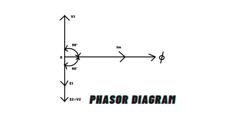
primary emf e1 and e2 lag behind flux Φ by 90° and their magnitude depands upon the number of primary and secondary turns.
above figure phasor diagram of ideal transformer on no load.since flux Φ is common to both the windings then it has to taken as a refernce phasor . it shows that the primary winding emf e1 and secondary winding emf e2 lag behind the flux by 90°. the otherside emf e1 and e2 both are in phase.but e1 is equal to v1 and out of phase respective 180degree out of phase with it.
in above block diagram we see that flux is contact linkage primary to Secondary and no Leakage flux exists. and in phase with magnetising current Im. in depth and easy of understand we see its phasor diagram.
Emf Equation Of A Transformer
voltage transformation ratio
for further study of induced emf we know that
the constant K is called voltage transformation ratio.thus if k=10
transformation ratio for ideal transformers
there is no losses at all.therefore volt -amperes input to the primary are equal to the output volt and amperes.
in the above formulas we can reach a conclusions that current is Inversely proportional to voltage. that causes if voltage increase then current decrease gradually upto voltage ratio.
in the above formulas we can reach a conclusions that current is Inversely proportional to voltage. that causes if voltage increase then current decrease gradually upto voltage ratio.
check out : Best Multimeter
ideal transformers on load
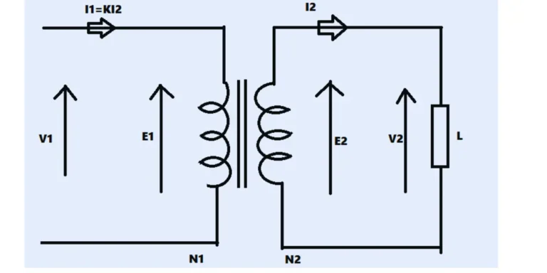
lets connect some load to secondary of ideal transformers which is assumed by L. the secondary emf e2 causes a current I2 to flow from Load.
the angle of load i2 leading or lagging it depends upon resistance and reactance of load. we consider here regular inductive load so that current i2 lag behind voltage v2.
The secondary current I2 sets up an mmf N2I2 which produced a flux in the opposite direction to the fluxoriginally setup in the primary by the magnetising current.
from above phasor diagram we know that secondary current I2 sets up some mmf N2I2 which produce a flux in the opposite direction to the flux originally set up in the primary by the magnetising current.this will change the flux in the core from the original value value.then flux flux in the core should not change change from the original value.
in order to fulfill this condition the primary must develop an mmf which exactly counter balance the seconadry emf N2I2.hence a primary current I1 must flow in condition to,
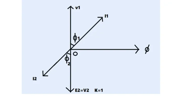
above diagram shown phasor diagrma of ideal transformers on load. kee in mind that the value of k is has been Assumed unity 1 . so , that primary phasor are equal tosecondary phasor .the secondary current I2 lags behind v2 by angle 2.
conclusion
above all diagram and figure explanation and some fact discussion we arrive at the end is an ideal transformer is there no,losses at all including winding on primary and secondary. and voltage of primary and secondary are in phase. and some condition also
powerfactor on the primary side = powerfactor on secondary side
there is no losses in ideal transformers input power is equal to secondary output power.
FAQs:
can ideal transformers exist in nature?
no any losses like winding losses , heating losses , leakage flux etc is called ideal but in a very minor winding loss exist in all transformer , then we cant get ideal but if we kept all Parameter strictly way and build a transformer then nearly ideal transformers we made but still not ideal.
ideal transformer is efficient than practical transformer?
definately , ideal transformer is efficient than practical transformer because it reduces losses.
can phasor diagram same for ideal and practicle Transformers?
not same , but some current lagging therebetween practical and ideal transformers.